By Abbas Al-Rubaye, Anthony Fortier & Calvin Feng
3D Conceptual Model of Digital School
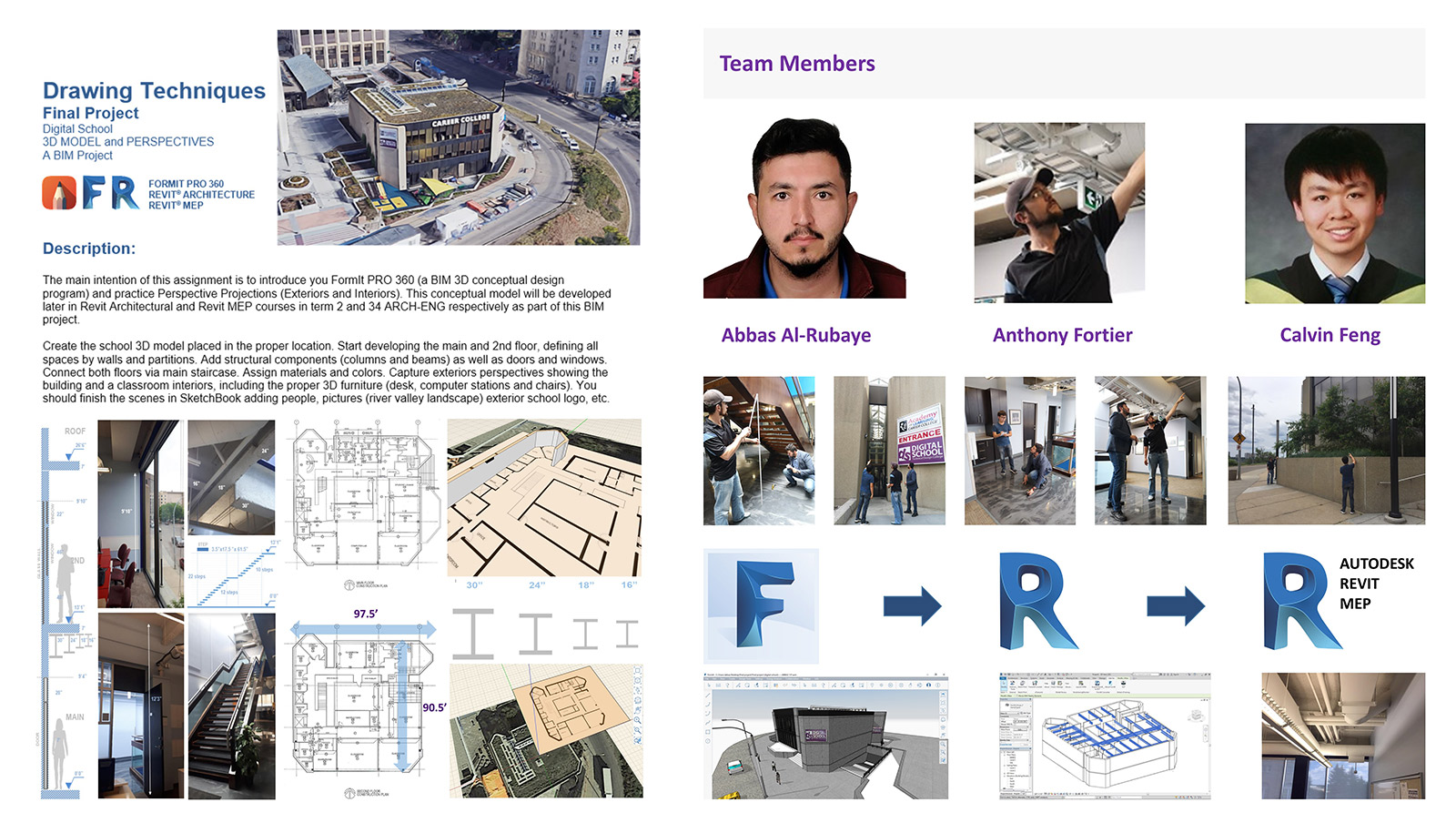
Team Members: Abbas Al-Rubaye, Anthony Fortier & Calvin Feng
Our Final Project
A s our final project of the first term at Digital School – which we are submitting for competition – we put together a conceptual 3D model using the BIM tool, FormIt Pro. Previous Digital School students had been tasked with modeling the iconic Farnsworth House as their final project – but not us!
When it came time to receive the assignment, we were informed that plans had changed. Professor Antonio Cuan, turned on a projection with an image of the very school we were sitting in. We were only given scaled floor plans to trace for the floors and walls, the heights of each floor, outside length and width of the building, and beam measurements. For everything else, we had to manually measure and research to determine the necessary information for the project. Being accurate with little information was a challenge, especially using a raster program, but a necessity for the project’s next steps.
Our class would forever be the pioneers of a new curriculum. Even with the school being the size that it is in comparison to the house, the only difference in execution was the size of the end product. The real challenge we face has yet to come. In Term Two we will be transferring the 3D model we created with FormIt Pro to another BIM tool: Revit Architecture. We will be utilizing the seamless integration between the two programs.
In Revit Architecture we will be refining our 3D models to be accurate representations of the space. Since walls and floors were traced from an imported picture, overall scale of the building, positions of doors, true positioning of structural beams and posts, and even the thickness of walls will be corrected. Once confirmed to be accurate, dimensioning will be applied.
Lastly, the project will move into Revit MEP for completion. Here, all of the mechanical, electrical, and plumbing is set to be redesigned using features such as clash detection to deliver a usable Project Information Model. Over the course of a year, we will have learned to systematically implement BIM processes and workflows. We will have created Level 1, Level 2, and Level 3 complete BIM files.
WATCH VIDEO


1- INTRODUCTION
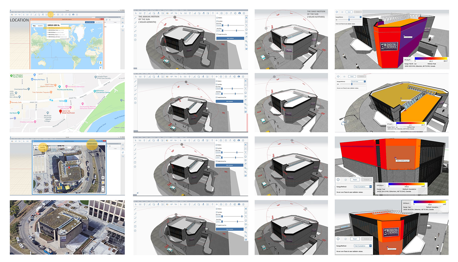
2- GEO LOCATION & SOLAR ANALYSIS
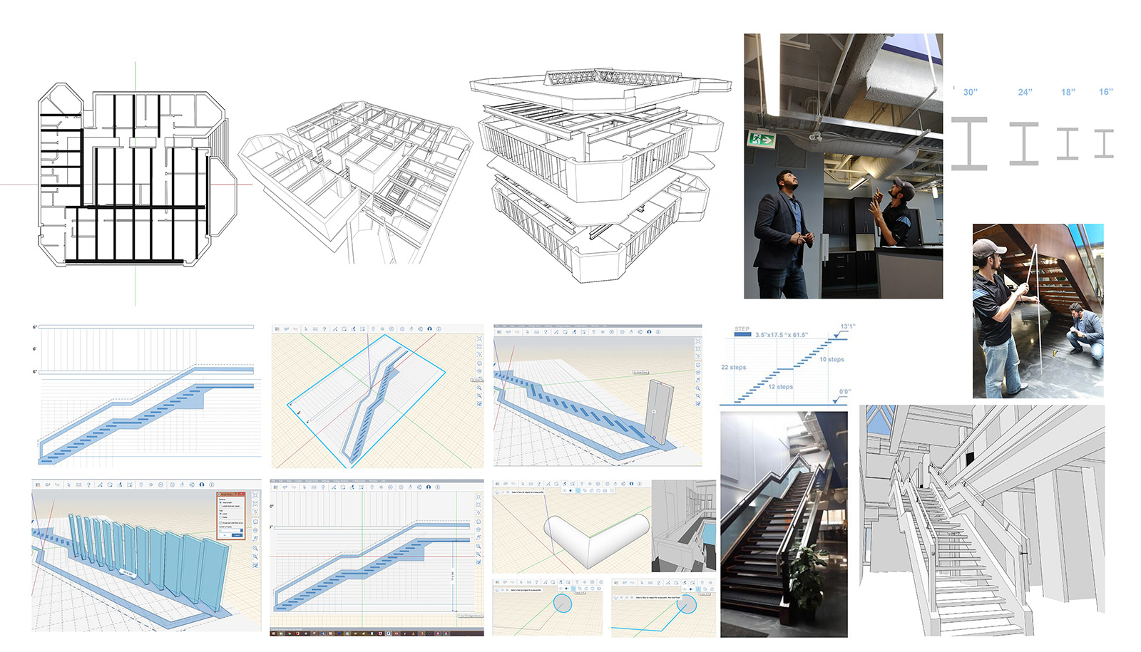
Before we could begin rendering the school, we first set our geographic location. This allows for a realistic representation of shadows for use when presenting the project, energy analysis to know when and where the building may be vulnerable to UV damage, as well as where extra insulation may need to be considered. After importing 2 scanned floor planned of the school, 1 for main floor and 1 for second, we discovered while scaling the image so our models would be accurate that the print itself was not perfectly to scale. Once corrected we traced the lines on the image for a 2D model that we could manipulate.
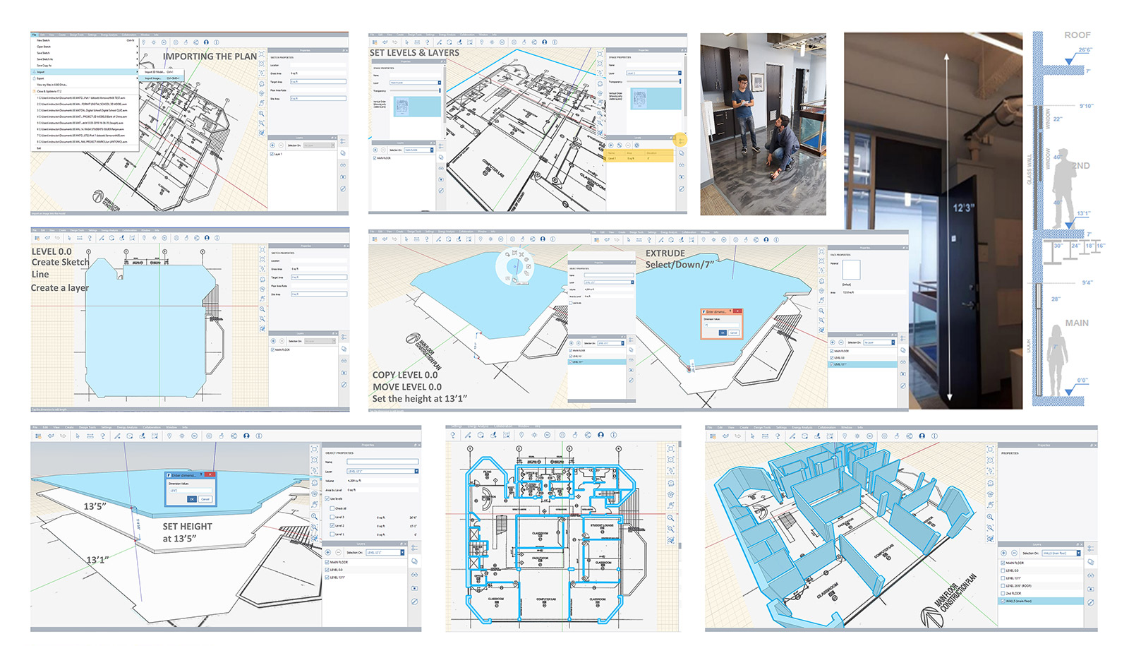
3 - LEVELS & LABELS
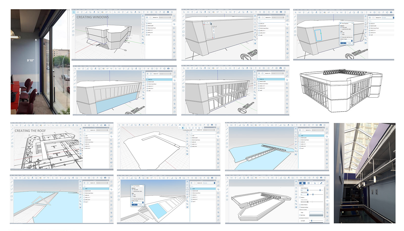
4- WINDOWS & ROOF
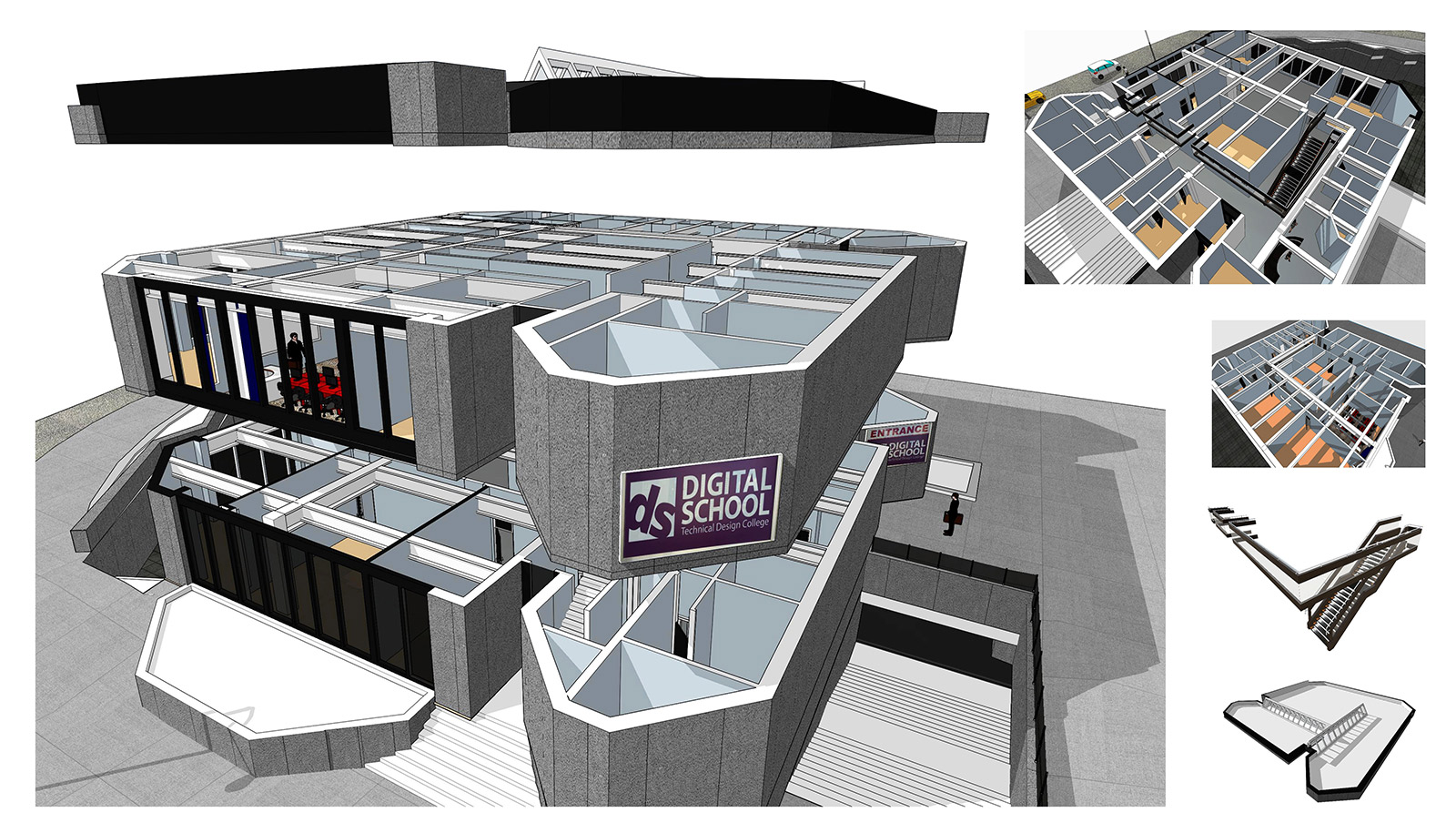
The move to 3D brought to light a habit that needs to be adopted in order to keep layers separate within the model. Anything 2 objects that are touching, but belong to separate layers, need to be grouped separately before any modifications can happen. If they are not grouped, any modification will join the objects across layers. Extruding walls allowed for special awareness and a realistic perception early in the project. Working with materials such as glass to install windows and skylights made the building start to look real even without adding any other textures yet.
Items such as the stairs are a prime example that there may be more than one way to deliver the same object. First there was drawing a grid to match the rise and run of the stairs, outlining the stringer on this grid, then after extruding 1 stair use array to create multiple copies of the stair before rotating the stringer vertical.
Next is Dynamo where the stringer still needs to be drawn, but the stairs themselves are created for you by setting all necessary measurements. The third technique used by our class was similar to the first, however instead of drawing a grid, the stringers were made for the stairs vertically, and then a single stair was created to be multiplied by the array command.
5 - STRUCTURAL COMPONENTS
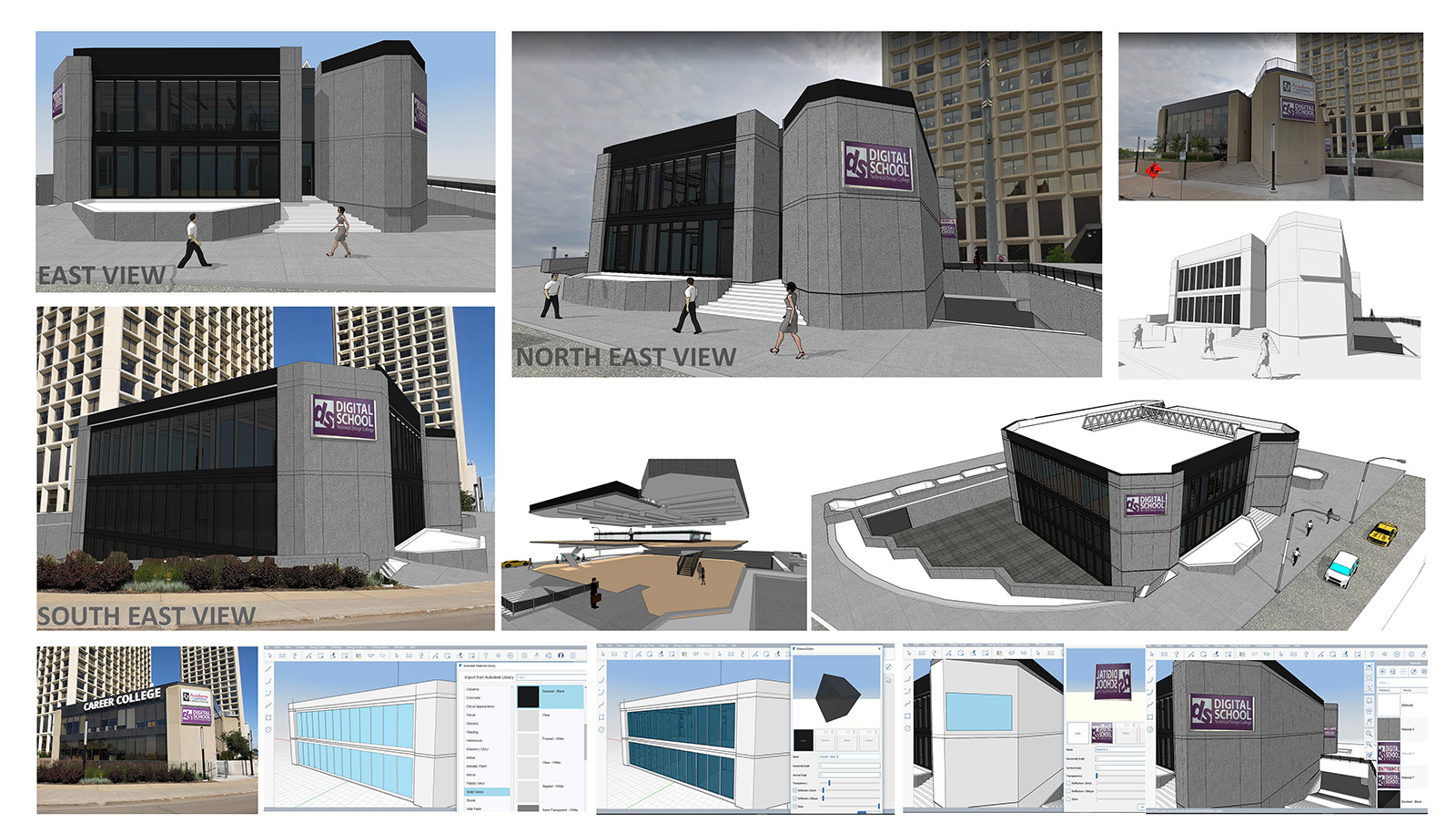
6- EXTERIOR SCENES
Once the basic structure of the building was complete, including estimated positions of structural beams, materials were added for color, texture, and even images for a life like finish. Some materials were simple, and just needed to be applied to a surface. Others however such as the signs on the outside of the building, needed to be captured as an image, edited to be the right scale, then imported. This is because in FormIt Pro you cannot rotate an imported image vertical. Once satisfied with our products, we set scenes to provide a virtual tour of the finished 3D model.
Rendering a 3D model as our first project inspired creativity and imagination that 2D will never be able to match. It caused a certain excitement that made the learning process fun. Enjoying what you are doing opens the mind to absorbing new information. This information is then kept readily available for future use. Over time the skills acquired in pleasant situations that are repeated become automatic responses requiring no conscious thought.
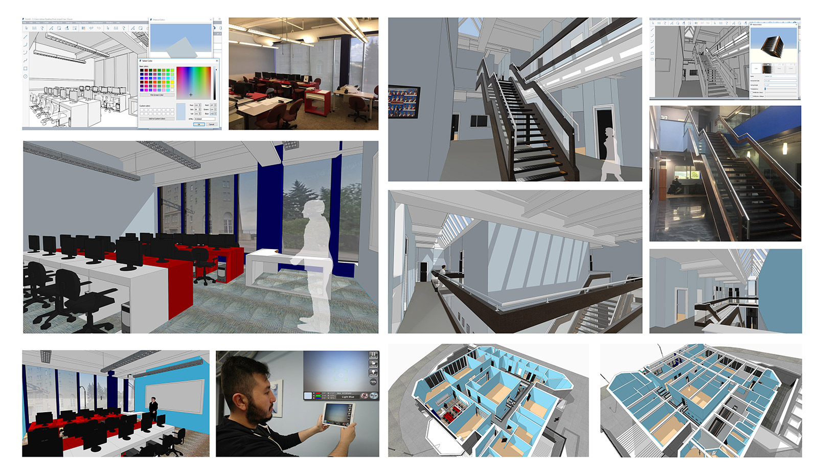
7 - INTERIOR SCENES
8- CONCLUSION
Participating in the early stages of a new AEC trend enhances this excitement. Fear and intimidation from complex programs are replaced by a drive to learn. In essence the learning process becomes a game that you want to get to the next level. When you enjoy the knowledge and skills passed on by instructors and our peers, learning to use BIM tools such as Revit MEP is not only an instant gratification, but also a healthy base to a strong career.